QubitPulseGenerator
Multi-Channel Programmable Pulse Generator for Qubit Control
Features
- Original
pulse_gencore preserved unchanged. multi_pulse_genwraps up to 4 independent channels with shared clock and reset.- Parallel register-style control interface with combinational reads and synchronous writes.
- Per-channel
width,period, andenablecontrol. - OR-ed
busyoutput for system-level arbitration. - Self-checking simulation benches for the scalar core and the multi-channel wrapper.
- Formal assertion module for
pulse_gen. - Python waveform generator that emits
docs/waveform.pngat 600 DPI.
Quick Start
git clone https://github.com/a0ax/QubitPulseGenerator.gitcd QubitPulseGenerator/scriptsmake sim wave
The waveform image is written to docs/waveform.png.
Modules
pulse_gen
Parameters
| Parameter | Default | Description |
| — | —: | — |
| WIDTH_BITS | 8 | Width register size |
| PERIOD_BITS | 16 | Period register size |
Ports
| Port | Direction | Width | Description |
| — | — | — | — |
| clk | input | 1 | Clock |
| rst_n | input | 1 | Active-low reset |
| enable | input | 1 | Enables pulse generation |
| width | input | WIDTH_BITS | High-time in cycles |
| period | input | PERIOD_BITS | Period in cycles |
| pulse | output | 1 | Generated pulse |
| busy | output | 1 | High while the generator is active |
Instantiation
pulse_gen #(
	.WIDTH_BITS(8),
	.PERIOD_BITS(16)
) u_pulse_gen (
	.clk(clk),
	.rst_n(rst_n),
	.enable(enable),
	.width(width),
	.period(period),
	.pulse(pulse),
	.busy(busy)
);
multi_pulse_gen
Parameters
| Parameter | Default | Description |
| — | —: | — |
| WIDTH_BITS | 8 | Shared width register size |
| PERIOD_BITS | 16 | Shared period register size |
| DATA_BITS | max(WIDTH_BITS, PERIOD_BITS) | Parallel bus width |
| NUM_CHANNELS | 4 | Number of instantiated channels |
Ports
| Port | Direction | Width | Description |
| — | — | — | — |
| clk | input | 1 | Shared clock |
| rst_n | input | 1 | Active-low reset |
| channel_sel | input | 2 | Channel selector |
| wr_en | input | 1 | Write strobe |
| addr | input | 2 | Register address: 0=width, 1=period, 2=control |
| wr_data | input | DATA_BITS | Write data |
| rd_data | output | DATA_BITS | Combinational read data |
| pulse_out | output | NUM_CHANNELS | Per-channel pulses |
| busy | output | 1 | OR of all channel busy signals |
Instantiation
multi_pulse_gen #(
	.WIDTH_BITS(8),
	.PERIOD_BITS(16),
	.NUM_CHANNELS(4)
) u_multi_pulse_gen (
	.clk(clk),
	.rst_n(rst_n),
	.channel_sel(channel_sel),
	.wr_en(wr_en),
	.addr(addr),
	.wr_data(wr_data),
	.rd_data(rd_data),
	.pulse_out(pulse_out),
	.busy(busy)
);
Simulation
Existing script
The legacy simulator script remains available for the scalar core:
cd scripts
vsim -c -do sim.do
or
cd scripts
vivado -mode batch -source sim.do
Scalar testbench
sim/tb_pulse_gen.sv is a bounded, self-checking testbench with edge cases and 50 randomized (width, period) pairs.
Multi-channel testbench
sim/tb_multi_pulse_gen.sv programs all four channels, checks register reads, verifies independent pulse streams, and exercises the OR-ed busy output.
Icarus Verilog flow
iverilog -g2012 -o build/tb_pulse_gen.vvp rtl/pulse_gen.sv sim/tb_pulse_gen.sv
vvp build/tb_pulse_gen.vvp

iverilog -g2012 -o build/tb_multi_pulse_gen.vvp rtl/pulse_gen.sv rtl/multi_pulse_gen.sv sim/tb_multi_pulse_gen.sv
vvp build/tb_multi_pulse_gen.vvp
Synthesis
Vivado can target either the scalar core or the multi-channel wrapper.
create_project pulse_gen ./build -part xc7a100tcsg324-1
add_files ../rtl/pulse_gen.sv
add_files ../rtl/multi_pulse_gen.sv
add_files -fileset constrs_1 ../constraints/pulse_gen.xdc
launch_runs impl_1 -to_step write_bitstream
wait_on_run impl_1
Use multi_pulse_gen as the top level when you want the multi-channel subsystem.
Testing
sim/tb_pulse_gen.svchecks reset, disabled behavior,width=0,period=0,width=period,width>period, enable toggling, reset during operation, and 50 randomized cases.sim/tb_multi_pulse_gen.svchecks register programming, readback, independent channel output timing, andbusyaggregation.sim/pulse_gen_assert.svcan be bound topulse_genfor formal or assertion-based simulation.
Waveform
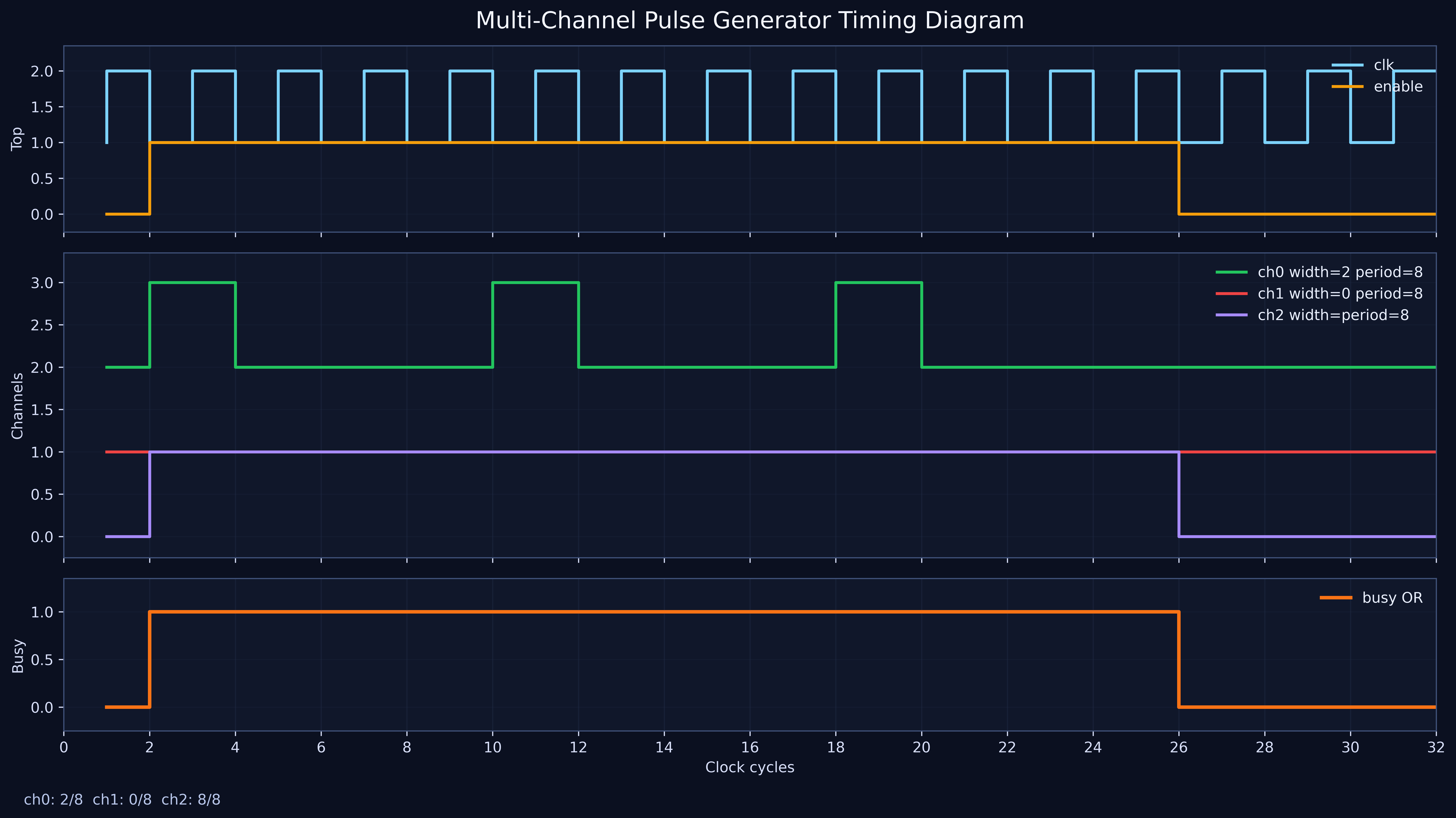
The generated timing diagram is shown below and is created by scripts/generate_waveform.py.
Timing Closure
report_timing_summary -delay_type max -report_unconstrained -max_paths 10 -file timing_summary.rpt
Verify in timing_summary.rpt that WNS >= 0 and Fmax exceeds 100 MHz.